

Design
SMC BMC materials offer exceptional flexibility to the designer: for example a design based on mouldable SMC BMC can produce a highly complex, multi-functional part that could not be realised in metals. First stage in the design process is to create a computer aided design (CAD), using numerical modelling such as finite element analysis (FEM).
SMC BMC properties are well known, which makes it a favourable choice for designers. With the mechanical properties, a designer can create a CAD model and simulate mechanical reliability using FEA and can rework the design as necessary.
Design BENEFITS OF SMC BMC
- SMC BMC closed sections can be designed to take the same loads as steel
- The coefficient of linear thermal expansion for SMC BMC is close to steel and aluminium
- The ‘spring-back’ associated with steel or aluminium does not exist with SMC BMC
- Low Profile Class A System shrinkage is zero or no more than ½ mm/m
- Tools are built directly from the designer’s mathematical calculations
- Read-through effects of SMC BMC are very low compared to thermoplastics
BASIC DESIGN CONSIDERATIONS
FOR SMC BMC COMPONENTS
- To increase moments of inertia use contoured surfaces
- Wherever possible in the design consider points of inertia e.g. styling lines, corrugations or ribs
- If panels are too thick this will further increase non-linear curing times
- Recommended outer panels: 2.0-3.0mm thickness
- Recommended inner panels: 2.0-3.5mm thickness
- Recommended curing times: 30 seconds to 45 seconds per mm thickness
- Maintain uniform wall thickness for uniform flow, uniform curing and the minimization of warpage and distortion.
- This also minimizes read-through where there are thickness changes (non-Class A design).
SMC BMC parts can be strengthened and made more rigid by incorporating ribs and bosses into the design. But ribs are not used on Class A outer panels because they can create sink marks (opposite) - localized depressions in the surface of moulded parts caused by the non-uniform shrinking of the SMC BMC during the cooling process. In cosmetically critical parts, they can be a serious problem. Sink marks are dependent on part geometry and material shrinkage rates. For Non class A component design, sink marks can be minimized or eliminated by the proper design of reinforcing ribs using the right combination of draft angle, radii and rib thickness as indicated in the diagram opposite.
BONDING
The physical properties of both the adhesive and the parts to be bonded needs to be considered during the design phase of a part. Typically bond flanges should range from 16 to 25mm. A minimum flange width of 6mm may be used on smaller parts such as spoilers and a minimum of 3mm clearance from the tangent should he allowed between the edge of the inner panel and the return flange on the outer panel. This allows for positive location in the fixture and adhesive de-roping.
BONDING FOR CLASS A
For Class A surfaces, especially high-visibility horizontal applications such as hood assemblies, it is preferable for the bond location to be restricted to the panel perimeter and surface contour changes. This greatly reduces the risk of bond read-through. Elastic, low modulus adhesives, can be used in such areas because, in most cases, these adhesive don’t have a high loading requirement - they are just acting as so called ‘antiflutter- adhesive’. All closures must he vented to prevent air from being trapped in the assembly. Trapped air might expand and distort the surface when exposed to paint oven temperatures. Vents can he provided by interrupting the adhesive line or by providing a vent hole.
Coefficient of
lienear thermal expansion (CLTE)
The slope of the line representing dimensional change as a function of temperature is known as the CLTE. SMC components require no specific attention in this respect compared to other materials, especially nonferrous metals like aluminium.
CLTE comparison
Steel
Aluminium
SMC
12 x 10-6/°C
24 x 10-6/°C
12-16 x 10-6/°C
BENCHMARKING
| Material | Steel | Al/Mg | Thermoplastics | SMC/BMC |
|---|---|---|---|---|
| Part consolidation | --- | º | +++ | +++ |
| Customizing | --- | --- | + | +++ |
| Corrosion resistance | --- | --- | ++ | +++ |
| Low weight design | --- | +++ | ++ | +++ |
| Fire resistance | +++ | (++) | --- | +++ |
| Specific stiffness | -- | + | -- | +++ |
| Water absorption | +++ | +++ | --- | + |
| Online paintability | +++ | +++ | -- | +++ |
| Temperature resistance | +++ | ++ | --- | ++ |
| Mass colouration | --- | --- | +++ | +++ |
| Recyclability | ++ | ++ | + | + |
| E-Permeability | --- | --- | +++ | +++ |
| Eco efficiency | -- | --- | º | ++ |
| +++ positive, --- negative, º neutral |
Sound dampening of various materials
| Material | Loss Factor |
|---|---|
| Aluminium | 7 x 10⁻⁵ |
| Steel | 2 x 10⁻⁵ |
| SMC | 0.40 |
| Polyamide | 0.16 |
The sound transmission loss from SMB/BMC parts is much better compared with aluminium. The loss factor for SMC is significantly higher than aluminium, meaning that SMC/BMC engine parts like valve covers and oil sumps contribute to reduced engine noise, harshness and vibration.
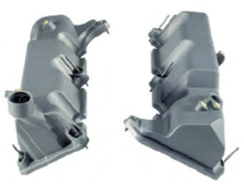
‘SMC/BMC valve covers and oil sumps feature significant sound dampening properties’

Follow us on
social networks